02
03
Pinewood Derby Stories and Photos from Maximum Velocity
04
05
15
16
19
20
21
22
23
24
25
26
27
28
31
32
33
34
Is Your Finish Line Providing Accurate Results?
(Throughout this article I have identified action items that track owners should take to make sure that the finish line provides accurate results.)
During our April race, a parent caught my attention and stated that the electronic finish line was not accurately identifying the finish order. I carefully watched the next several races, and did detect a discrepancy. Was the finish line malfunctioning? Read on to find out!
FINISH LINE PRINCIPLE
Electronic finish lines use optical sensors(1) to determine when a car crosses the finish line. However, there is one fundamental principle of finish lines that must be understood;
Electronic Finish lines select the finish order based on the sequence in which the light sensors are activated, not necessarily on the order in which the cars cross the finish line.
To better explain how this is true, we must consider sensor, car, and track characteristics which would cause the finish line to record a finish order which is not the same order that the cars crossed the finish line.
SENSORS
-- Characteristics --
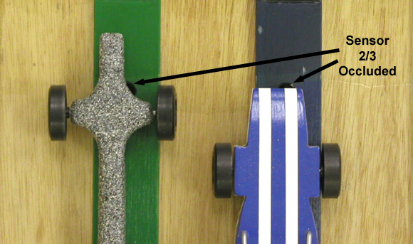
Optical sensors(2) trip when the amount of light entering the sensor drops below a certain threshold. This light blockage (caused by the car passing between the sensor and light source) is known as 'occlusion' (see Figure 1). The amount of occlusion required varies by manufacturer and from sensor to sensor. Manufacturers of finish lines generally test the sensors to make sure that the amount of occlusion required to trip the sensor is consistent within the finish line unit. If the sensors are not consistent, then the finish line results will be less than accurate (i.e., a sensor with a lower occlusion percentage will trip earlier, giving an advantage to the lane on which it is mounted).
Figure 1 - Sensor Occlusion
I tested the occlusion of two electronic finish lines from two major manufacturers. On one, the amount of occlusion required was about thirty-three percent, while the other was about sixty-six percent. Fortunately, in both cases the occlusion percentage was consistent within the unit.
ACTION 1: Check the occlusion percentage for your sensors to make sure they are consistent.
-- Placement --
In order for a finish line to accurately judge a race, the sensor holes must be drilled in a straight line, perpendicular to the track. In addition, the sensors must be mounted accurately in the hole. Generally, the sensor is smaller than the hole in the track. For accurate results, the sensor must be centered in the track hole.
ACTION 2: Verify sensor alignment and placement.
-- Lighting --
Most sensors are infrared (IR) sensitive, and are generally not affected by room lighting or camera flashes.(3) However, reflective surfaces on the track and car can change the amount of IR entering the sensor. This can be limited by painting a non-reflective black stripe across the finish line area.(4) Light variance can further be controlled by reducing the diameter of the sensor hole. This can be accomplished by inserting a bushing with a small aperture, sized to fit the hole. (see Figure 2)
Figure 2 - Bushing With Small Aperture Inserted Into Sensor Hole
ACTION 3: Reduce reflection with black, non-reflective paint, and reduced apertures.
TRACK CHARACTERISTICS
Most tracks use a raised center guide strip to hold the car on the track. The width of the guide strip, determines the amount of deviation from the center line that the car is allowed to travel.
The typical guide strip width used today is 1-5/8 inches (see Figure 3). This width effectively limits the side to side travel of the car.
Figure 3 - Guide Strip Width on BestTrack and Freedom Track
However, some tracks have a lane guide strip of 1-3/8 inches. Figure 4 shows a photo of a homemade track that was based on plans provided by Awana. Some plans on the Internet also call for a 1-3/8 inches lane guide strip.
Figure 4 - Guide Strip Width on Homemade Track
Narrower lane guides allow the car to deviate a greater distance from centerline.(5) For a car with a full-width (or reasonably wide) front end this deviation causes no issues at the finish line. However, cars with narrow noses can have problems with narrower guide strips.
Consider a car with a 1/2 inch wide nose crossing the finish line on a track with 1-3/8 lane guides. The finish line sensors require a 66 percent occlusion. If the car is positioned at the center of the track when the finish line is crossed, then the finish will be properly registered. However, if the car is riding the rail, then the car may not register properly. In Figure 5, the car has crossed the finish line, but the sensor has not tripped (not 66 percent occluded). This car will need to proceed nearly 1-1/2 inches past the finish line before the sensor trips. Figure 6 shows a finish between this car and a car with a wider nose.
Figure 5 - Narrow Nose Car Not Tripping the Sensor
Figure 6 - Finish between Narrow and Wide-Nose Cars
In this case, the narrow lane guide, the narrow nose on the car, and the 66 percent occlusion requirement add together to create a major discrepancy. But note that narrow nose cars can cause discrepancies under less severe circumstances. When the two cars in Figure 6 were tested on a track with a lane guide measuring 1-5/8 inches, and a sensor requiring a 33 percent occlusion, the narrow nose car still had a 1/4 inch disadvantage when it rode the rail.(6)
If alerted to the narrow nose issue, entrants can choose to either design the car with a wider nose, or install a nose wing on the car.
ACTION 4: Test your track for discrepancies when using narrow-nosed cars. If a discrepancy exists, insert a note into race rules and handouts alerting the builder of the issue.
CAR CHARACTERISTICS
In addition to a narrow nose, other car characteristics can result in finish line discrepancies. These include:
1. Reflective surface on the underside of the car (delays sensor trip due to reflective light)
2. High-nose on the car (allows more reflective light, possibly delaying the sensor trip)
3. Narrow 'Cheater Bar' on the front of the car (not enough material to occlude the sensor) - See Figure 7.
Figure 7 - Spoiler May Not Trip Sensor
ACTION 5: Alert builders of any car characteristics which can result in finish line discrepancies.
CONCLUSION
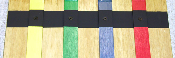
After discovering these issues with our track I painted a flat black stripe across the finish line and inserted bushings with narrow apertures into the sensor holes (see Figure 8). This has eliminated light reflection issues.
Figure 8 - Modified Finish Line
In addition, I plan to put an alert in the race rules regarding narrow-nose cars; I will recommend a minimum of a 3/4 inch wide front end for accurate judging. Furthermore, when our group chooses to invest in a new track, we will choose a track with wider lane guides, and preferably, an electronic finish line with a lower sensor occlusion requirement.
If you are a race leader, then I encourage you to test your equipment and take the necessary actions to ensure a fair race. If you are competing, then consider using a car with a wider nose and painting the bottom of the car flat black.
(1) With one known exception: the Supertimer uses physical switches to determine the finish order.
(2) For more information on sensor occlusion and timer accuracy, please refer to Volume 5, Issue 11, "Pinewood Derby Timer Considerations".
(3) Infrared sensors are not intended for outdoor use, as the sun produces high levels of infrared light which can affect the sensors. A sunlight option is available on the "Judge" timer at:
http://www.newdirections.ws
(4) Entrants can also reduce this issue by painting the bottom of the car flat black. I used Krylon-brand "Ultra-flat Black" with success.
(5) The amount of wheel hub to car body gap also affects the amount of deviation. I am assuming a normal gap of 0.035 inch.
(6) Generally, a car nose width of 3/4 inch is sufficient for tracks with a 1-5/8 inch lane guide.